AutoRob


AutoRob

Introduction to Autonomous Robotics


Michigan ROB 380 / EECS 367


Mobile Manipulation Systems


Michigan ROB 511


Winter 2025


Introduction

AutoRob is an introduction to the computational foundations of autonomous robotics for programming modern mobile manipulation systems. AutoRob covers fundamental concepts in autonomous robotics for the kinematic modeling of arbitrary open-chain articulated robots and algorithmic reasoning for autonomous path and motion planning, and brief coverage of dynamics and motion control. These core concepts are contextualized through their instantiation in modern robot operating systems, such as ROS and LCM. AutoRob covers some of the fundamental concepts in computing, common to a second semester data structures course, in the context of robot reasoning, but without analysis of computational complexity. The AutoRob learning objectives are geared to ensure students completing the course are fluent programmers capable of computational thought and can develop full-stack mobile manipulation software systems.

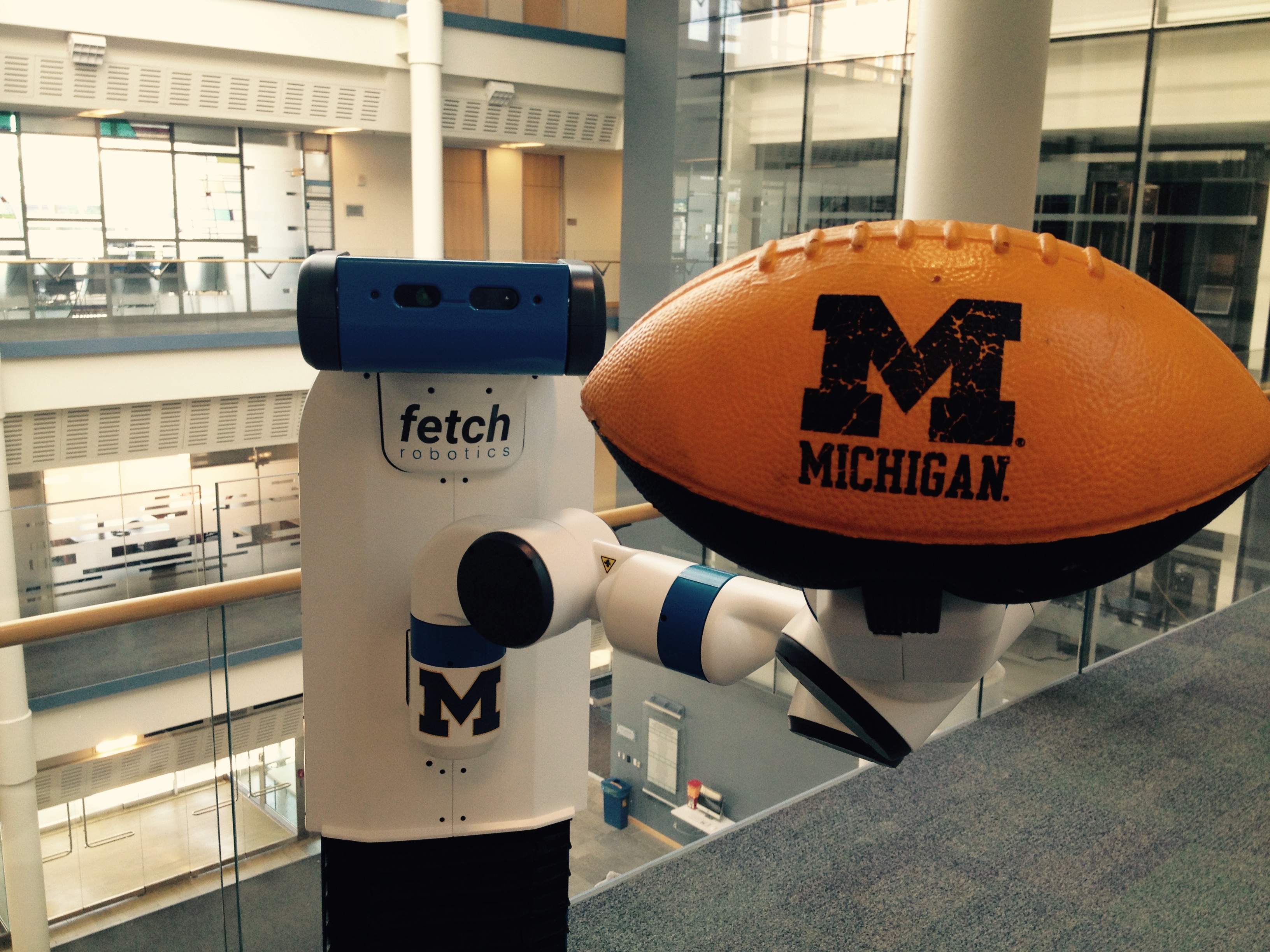
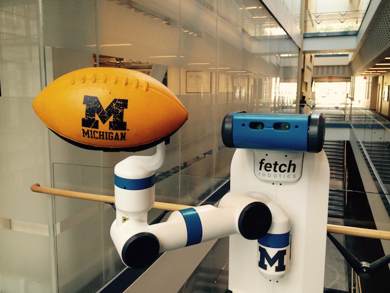
The AutoRob course can be thought of as an exploration into the foundation for reasoning and computation by autonomous robots capable of mobility and dexterity. That is, given a robot as a machine with sensing, actuation, and computation, how do we build computational models, algorithms, software implementations that allow the robot to function autonomously, especially for pick-and-place tasks? Such computation involves functions for robots to perceive the world (as covered in Robotics 330, EECS 467, EECS 442, or EECS 542), make decisions towards achieving a given objective (this class as well as EECS 492), transforming action into motor commands (as covered in Robotics 310, Robotics 311, or EECS 367), and usably working with human users (as covered in Robotics 340). Computationally, these functions form the basis of the sense-plan-act paradigm that defines the discipline of robotics as the study of embodied intelligence, as described by Brooks. Embodied intelligence allows for understanding and extending concepts essential for modern robotics, especially mobile manipulators such as the pictured Fetch robot.

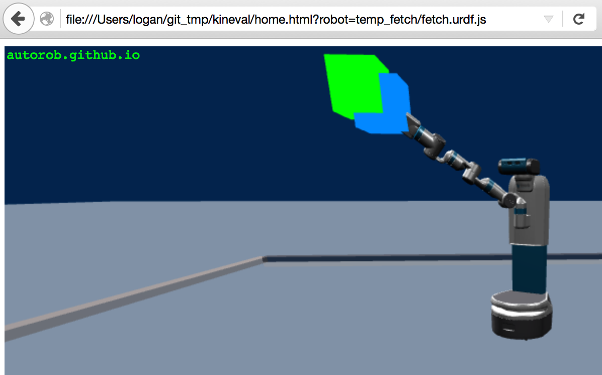
AutoRob projects ground course concepts through implementation in JavaScript/HTML5 supported by the KinEval code stencil (snapshot below from Mozilla Firefox), as well as tutorials for the ROS robot operating system and the rosbridge robot messaging protocol. These projects will coverrobot middleware architectures and publish-subscribe messaging models, graph search path planning (A* algorithm), basic physical simulation (Lagrangian dynamics, numerical integrators), proportional-integral-derivative (PID) control, forward kinematics (3D geometric matrix transforms, matrix stack composition of transforms, axis-angle rotation by quaternions), inverse kinematics (gradient descent optimization, geometric Jacobian), and motion planning (simple collision detection, sampling-based motion planning). Additional topics that could be covered include network socket programming, JSON object parsing, potential field navigation, Cyclic Coordinate Descent, Newton-Euler dynamics, task and mission planning, Bayesian filtering, and Monte Carlo localization.

KinEval code stencil and programming framework

AutoRob projects will use the KinEval code stencil that roughly follows conventions and structures from the Robot Operating System (ROS) and Robot Web Tools (RWT) software frameworks, as widely used across robotics. These conventions include the URDF kinematic modeling format, ROS topic structure, and the rosbridge protocol for JSON-based messaging. KinEval uses threejs for in-browser 3D rendering. Projects also make use of the Numeric Javascript external library (or math.js) for select matrix routines, although other math support libraries are being explored. Auxiliary code examples and stencils will often use the jsfiddle development environment.

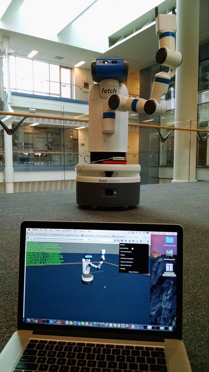
You will use an actual robot (at least once)!

While AutoRob projects will be mostly in simulation, KinEval allows for your code to work with any robot that supports the rosbridge protocol, which includes any robot running ROS. Given a URDF description, the code you produce for AutoRob will allow you to view and control the motion of any mobile manipulation robot with rigid links. Your code will also be able to access the sensors and other software services of the robot for your continued work as a roboticist.


Course Staff and Office Hours

Course Instructors

Staff Image

Chad Jenkins
ocj@umich
GitHub: ohseejay
Office Hours: by appointment
Office: Robotics 2236

Staff Image

Elizabeth Goeddel
mamantov@umich
GitHub: emgoeddel
Office Hours: Tuesday 9:30 - 11:30 a.m.
Location: 2000 Robotics

Graduate Student Instructors

Staff Image

Isaac Madhavaram
imadhav@umich
GitHub: imadhav21
Office Hours: Wednesday 2:00 - 4:00 p.m.
Location: 2000 Robotics

Haoran Zhang
haoranwh@umich
GitHub: HaoranZhangumich
Office Hours: Friday 4:30 - 6:30 p.m.
Location: 2000 Robotics

Nikhil Sridhar
niksrid@umich
GitHub: theonlynick0430
Office Hours: Tuesday 3:30 - 5:30 p.m.
Location: 2320 Robotics

Office Hours Calendar

Winter 2025 Course Structure

This semester, the AutoRob course is offered in a synchronous in-person format across a number of sections this semester: two undergraduate in-person sections (Robotics 380 and EECS 367) and an in-person graduate section (Robotics 511).

Course Meetings:
Monday 4:30-7:20pm Eastern, Chrysler Building 133

Laboratory Sections
Friday 2:30-4:20pm Eastern, Chrysler Building 133

The AutoRob office hours queue hosted by EECS will be used to manage queueing for course office hours.

Discussion Services

Piazza

The AutoRob Course Piazza workspace will be the primary service for course-related discussion threads and announcements.

Course Schedule (tentative and subject to change)

Previously recorded slides and lecture recordings are provided for asynchronous and optional parts of the course, as well as preview versions of lectures.


Project 1: Path Planning

Due 3:00pm, Monday, January 27, 2025

Project 1 instructions can be found HERE.


Project 2: Pendularm

Due 3:00pm, Monday, February 10, 2025

Project 2 instructions can be found HERE.


Project 3: Forward Kinematics

Due 11:59pm, Friday, February 28, 2025

Project 3 instructions can be found HERE.


Material beyond this point has not been assigned. The descriptions below are unofficial and tentative.


Assignment 4: Robot FSM Dance Contest

Due 4:00pm, Monday, March 11, 2024

Executing choreographed motion is the most common use of current robots. Robot choreography is predominantly expressed as a sequence of setpoints (or desired states) for the robot to achieve in its motion execution. This form of robot control can be found among a variety of scenarios, such as robot dancing (video below), GPS navigation of autonomous drones, and automated manufacturing. General to these robot choreography scenarios is a given setpoint controller (such as our PID controller from Pendularm) and a sequence controller (which we will now create).

For this assignment, you will build your own robot choreography system. This choreography system will enable a robot to execute a dance routine by adding motor rotation to its joints and creating a Finite State Machine (FSM) controller over pose setpoints. Your FK implementation will be extended to consider angular rotation about each joint axis using quaternions for axis-angle rotation. The positioning of each joint with respect to a given pose setpoint will be controlled by a simple P servo implementation (based on the Pendularm assignment). You will implement an FSM controller to update the current pose setpoint based on the robot's current state and predetermined sequence of setpoints. For a single robot, you will choreograph a dance for the robot by creating an FSM with your design of pose setpoints and an execution sequence.

This controller for the "mr2" example robot was a poor attempt at robot Saturday Night Fever (please do better):

This updated dance controller for the Fetch robot is a bit better, but still very far from optimal:

Features Overview

This assignment requires the following features to be implemented in the corresponding files in your repository:

Points distributions for these features can be found in the project rubric section. More details about each of these features and the implementation process are given below.

Joint Axis Rotation and Interactive Joint Control

Going beyond the joint properties you worked with in Assignment 3, each joint of the robot now needs several additional properties for joint rotation and control. These joint properties for the current angle rotation (".angle"), applied control (".control"), and servo parameters (".servo") have already been created within the function kineval.initRobotJoints(). The joint's angle will be used to calculate a rotation about the joint's (normal) axis of rotation vector, specified in the ".axis" field. To complete an implementation of 3D rotation due to joint movement, you will need to first implement basic quaternion functions in "kineval/kineval_quaternion.js" then extend your FK implementation in "kineval/kineval_forward_kinematics.js" to account for the additional rotations.

If joint axis rotation is implemented correctly, you should be able to use the 'u' and 'i' keys to move the currently active joint. These keys respectively decrement and increment the ".control" field of the active joint. Through the function kineval.applyControls(), this control value effectively adds an angular displacement to the joint angle.

Interactive Base Movement Controls

The user interface also enables controlling the global position and orientation of the robot base. In addition to joint updates, the system update function kineval.applyControls() also updates the base state (in robot.origin) with respect to its controls (specified in robot.controls). With the support function kineval.handleUserInput(), the 'wasd' keys are purposed to move the robot on the ground plane, with 'q' and 'e' keys for lateral base movement. In order for these keys to behave properly, you will need to add code to update variables that store the heading and lateral directions of the robot base: robot_heading and robot_lateral. These vectors need to be computed within your FK implementation in "kineval/kineval_forward_kinematics.js" and stored as global variables. They express the directions of the robot base's z-axis and x-axis in the global frame, respectively. Each of these variables should be a homogeneous 3D vector stored as a 2D array.

If robot_heading and robot_lateral are implemented properly, the robot should now be interactively controllable in the ground plane using the keys described in the previous paragraph.

Pose Setpoint Controller

Once joint axis rotation is implemented, you will implement a proportional setpoint controller for the robot joints in function kineval.robotArmControllerSetpoint() within "kineval/kineval_servo_control.js". The desired angle for a joint 'JointX' is stored in kineval.params.setpoint_target['JointX'] as a scalar by the FSM controller or keyboard input. The setpoint controller should take this desired angle, the joint's current angle (".angle"), and servo gains (specified in the ".servo" object) to set the control (".control") for each joint. All of these joint object properties are initialized in the function kineval.initRobotJoints() in "kineval/kineval_robot_init_joints.js". Note that the "servo.d_gain" is not used in this assignment; it is for advanced extensions.

Once you have implemented the control function described above, you can enable the conroller by either holding down the 'o' key or selecting 'persist_pd' from the UI. With the controller enabled, the robot will attempt to reach the current setpoint. One setpoint is provided with the stencil code: the zero pose, where all joint angles are zero. Pressing the '0' key sets the current setpoint to the zero setpoint.

Besides the zero setpoint, up to 9 other arbitrary pose setpoints can be stored by KinEval (in kineval.setpoints) for pose control. You can edit kineval.setpoints in your code for testing and/or for the FSM controller (see below), but the current robot pose can also be interactively stored into the setpoint list by pressing "Shift+number_key" (e.g., "Shift+1" would store the current robot pose as setpoint 1). You can then select any of the stored setpoints to be the current control target by pressing one of the non-zero number keys [1-9] that corresponds to a previously-stored setpoint. At any time, the currently stored setpoints can be output to the console as JavaScript code using the JSON.stringify function for the setpoint object: "JSON.stringify(kineval.setpoints);". Once you have found the setpoints needed to implement your desired dance, this setpoint array can be included in your code as part of your dance controller.

Since you will need to implement your setpoint controller before your FSM controller, for additional testing of your setpoint controller, a "clock movement" FSM controller has been provided as the function setpointClockMovement() in "kineval/kineval_servo_control.js". This function can be invoked by holding down the 'c' key or from the UI. This controller goes well with this song.

FSM Controller

Once your pose setpoint controller is working, an FSM controller should be implemented in the function kineval.setpointDanceSequence() in "kineval/kineval_servo_control.js". The reference implementation switches between the pose setpoints in kineval.setpoints based on two additional pieces of data: an array of indices (kineval.params.dance_sequence_index) and the current pose index (kineval.params.dance_pose_index). kineval.params.dance_sequence_index will tell your FSM the order in which the setpoints in kineval.setpoints should be selected to be the control target. Note that using this convention allows you to easily select the same setpoint multiple times to produce repetition in your dance. kineval.params.dance_pose_index is used to keep track of the current index within the dance pose sequence.

If this recommended variable convention is not used, the following line in "kineval/kineval_userinput.js" will require modification:


if (kineval.params.update_pd_dance)
    textbar.innerHTML += "executing dance routine, pose " + kineval.params.dance_pose_index + " of " + kineval.params.dance_sequence_index.length;

To complete your dance controller, choreograph a dance by initializing kineval.setpoints with the poses for your dance and kineval.params.dance_sequence_index with the pose ordering. You should initialize these data structures within the my_init() function in "home.html". Once you have the poses and sequence for your dance initialized, when you select both "persist_pd" and "update_pd_dance" in the UI, you should see the robot move through the setpoints of your dance.

Graduate Section Requirements

Students in the graduate section of AutoRob must implement the assignment as described above for the Fetch and Baxter robots with two additional requirements: 1) proper implementation of all joint types in the robot descriptions and 2) proper enforcement of joint limits for the robot descriptions. and 3) integration (via rosbridge) of their code with ROS or a Gazebo simulation of the Fetch.

The urdf.js files for these robots, included in the provided code stencil, contain joints with with various types that correspond to different types of motion:

Joints are considered to be continuous as the default. Joints with undefined motion types must be treated as continuous joints. The graduate section features for this assignment will be complete when your implementation correctly handles the direction of motion (rotation or translation) and limits of all of the above types of joints.

rosbridge allows your code can interface with any robot (or simulated robot) running rosbridge/ROS using the function kineval.rosbridge() in "kineval/kineval_rosbridge.js". This code requires that the rosbridge_server package is running in a ROS run-time environment and listening on a websocket port, such as for ws://fetch7:9090. If your FK implementation is working properly, the model of your robot in the browser will update along with the motion of the robot based on the topic subscription and callback. This functionality works seamlessly between real and simulated robots. Although this will not be done for this class, to control the robot arm, a rosbridge publisher must be written to update the ROS topic "/arm_controller/follow_joint_trajectory/goal" with a message of type "control_msgs/FollowJointTrajectoryActionGoal".

Machines running rosbridge, ROS, and Gazebo for the Fetch will be available during special sessions of the class. Students are encouraged to install and run the Fetch simulator on their own machines based on this tutorial.

Robot FSM Dance Showcase

Students in the graduate section are required to present in the Robot Dance FSM Showcase in class on March 11. Students in the undergraduate section can earn one additional extension point by presenting in this showcase. Information for showcase presentations will be communicated through the class discussion channels.

Advanced Extensions

Of the possible advanced extension points, one additional point for this assignment can be earned by adding the capability of displaying laser scans from a real or simulated Fetch robot.

Of the possible advanced extension points, four additional points for this assignment can be earned by adding the capability of displaying 3D point clouds from a real or simulated Fetch robot and computing surface normals about each point.

Of the possible advanced extension points, four additional points for this assignment can be earned by implementing dynamical simulation through the recursive Newton-Euler algorithm (Spong Ch.7). This dynamical simulation update be implemented as function kineval.updateDynamicsNewtonEuler() in the file "kineval/kineval_controls.js". In "home.html", the call to kineval.updateDynamicsNewtonEuler() should replace the call purely kinematic update in kineval.applyControls().

Of the possible advanced extension points, five additional points for this assignment can be earned by developing and implementing a maximal coordinate dynamical simulation of biped hopper with links as 3D rigid bodies, similar to those in "On The Run" by Raibert and Hodgins at the MIT Leg Lab. This maximal coordinate pendulum implementation should be contained within the subdirectory "hopper_3d" with an "index.html" file that can be open to execute the simulation.

Project Submission

For turning in your assignment, push your updated code to the master branch in your repository.

Assignment 5: Inverse Kinematics

Due 11:59pm, Monday, March 25, 2024

Although effective, robot choreography in configuration space is super tedious and inefficient. This difficulty is primarily due to posing each joint of the robot at each setpoint. Further, changing one joint often requires updating several other joints due to the nature of kinematic dependencies. Inverse kinematics (IK) offers a much easier and efficient alternative. With IK implemented, we only need to pose the endeffector in a common workspace, and the states of the joints in configuration space are automatically inferred. IK is also important when we care about the "tool tip" of an instrument being used by a robot. One such example is a robot using marker to draw a picture, such as in the PR2 Portrait Bot Project below:

For this assignment, you will now control your robot to reach to a given point in space through inverse kinematics for position control of the robot endeffector. Inverse kinematics will be implemented through gradient descent optimization with both the Jacobian Transpose and Jacobian Pseudoinverse methods, although only one will be invoked at run-time.

As shown in the video below, if successful, your robot will be able to continually place its endeffector (indicated by the blue cube) exactly on the reachable target location (indicated by the green cube), regardless of the robot's specific configuration:

Features Overview

This assignment requires the following features to be implemented in the corresponding files in your repository:

Points distributions for these features can be found in the project rubric section. More details about each of these features and the implementation process are given below.

Matrix Pseudoinverse Function

You will need to implement one additional matrix helper function in "kineval/kineval_matrix.js" for this assignment: matrix_pseudoinverse. This method will be necessary for the pseudoinverse version of gradient descent (see below). For this helper function, you are allowed to use a library function for matrix inversion, which can be invoked by using the provided routine numeric.inv(mat), available through numericjs.

Core IK Function

The core of this assignment is to complete the kineval.iterateIK() function in the file kineval/kineval_inverse_kinematics.js. This function is invoked within the function kineval.inverseKinematics() with three arguments:

From these arguments and the current robot configuration, the kineval.iterateIK() function will compute controls for each joint. Upon update of the joints, these controls will move the configuration and endeffector of the robot closer to the target.

Important: Students in an undergraduate section are expected to implement inverse kinematics for only the position, not the orientation, of the endeffector.

kineval.iterateIK() should also respect global parameters for using the Jacobian pseudoinverse (through boolean parameter kineval.params.ik_pseudoinverse) and step length of the IK iteration (through real-valued parameter kineval.params.ik_steplength). Note that these parameters can be changed through the user interface (under Inverse Kinematics). KinEval also maintains the current endeffector target information in the kineval.params.ik_target parameter.

IK iterations can be invoked through the user interface (Inverse Kinematics->persist_ik) or by holding down the 'p' key. Further, the 'r'/'f' keys will move the target location up/down. You can also move the robot relative to the target using the robot base controls. When performing IK iterations, the endeffector and its target pose will be rendered as cube geometries in blue and green, respectively.

For your code to work with the CI grader, you will need to set three global variables in kineval.iterateIK(): robot.dx, robot.jacobian, and robot.dq. There is a comment in "kineval/kineval_inverse_kinematics.js" that specifies what each of these variables should hold. Please note that robot.dx and robot.jacobian should both have six rows, even if you are doing position-only IK.

In implementing this IK routine, please also remember the following:

IK Random Trial

All students in the AutoRob course are expected to run their IK controller with the random trial feature in the KinEval stencil. The IK random trial is executed through the function kineval.randomizeIKtrial() in the file "kineval/kineval_inverse_kinematics.js". This function is incomplete in the provided stencil. Code for this function to properly run the random trial will be made available in the assignment 5 discussion channel. Once you have copied the necessary code into this function, you will be able to test your code on random trials by first selecting persist_ik (under Inverse Kinematics) then selecting execute (under Inverse Kinematics->IK Random Trial) from the user interface.

Graduate Section Requirement

Students enrolled in the graduate section of AutoRob will implement inverse kinematics for both the position and orientation of the endeffector, namely for the Fetch robot. The default IK behavior will be position-only endeffector control. Both endeffector position and orientation should be controlled when the boolean parameter kineval.params.ik_orientation_included is set to true, which can be done through the user interface (Inverse Kinematics->ik_orientation_included).

In order to handle the orientation of the endeffector in your IK implementation, you will need to calculate the orientation part of the error term, which will require you to implement a conversion from a rotation matrix to Euler angles. You may find an online reference to inform your implementation of this conversion (please cite it in a comment in your code) or develop your own approach to the conversion calculation. Completing this conversion is a necessary step for including orientation in your IK implementation, and it also fulfills the "Euler angle conversion" feature.

Advanced Extensions

Of the possible advanced extension points, one extension point for this assignment can be earned by reaching to 100 targets in a random trial within 60 seconds. A video of this execution must be provided to demonstrate this achievement. This video file should be in the repository root directory with the name "IK100in60" and appropriate file extension.

Of the possible advanced extension points, three extension points for this assignment can be earned by implementing the Cyclic Coordinate Descent (CCD) inverse kinematics algorithm by Wang and Chen (1991). This function should be implemented in the file "kineval/kineval_inverse_kinematics.js" as another option within the function kineval.iterateIK().

Of the possible advanced extension points, three extension points for this assignment can be earned by implementing downhill simplex optimization to perform inverse kinematics. This function should be implemented in the file "kineval/kineval_inverse_kinematics.js" as another option within the function kineval.iterateIK().

Of the possible advanced extension points, one extension point for this assignment can be earned by implementing stochastic gradient descent to perform inverse kinematics. This function should be implemented in the file "kineval/kineval_inverse_kinematics.js" as another option within the function kineval.iterateIK().

Of the possible advanced extension points, four extension points for this assignment can be earned by implementing resolved-rate inverse kinematics with null space constraints to respect joint limits. This function should be implemented in the file "kineval/kineval_inverse_kinematics.js" as another option within the function kineval.iterateIK().

Of the possible advanced extension points, one extension point can be earned by implementing a closed-form inverse kinematics solution for the RexArm 4-DOF robot arm, which can be used later projects in EECS 467 (Autonomous Robotics Laboratory).

Of the possible advanced extension points, four extension points for this assignment can be earned by extending your IK controller to use potential fields to avoid collisions.

Of the possible advanced extension points, one extension point for this assignment can be earned by implementing a search mechanism to automatically find appropriate PID gains for the Pendularm. This implementation should be placed in the file "project_pendularm/pendularm1_gainsearch.html" and allow for arbitrary initial PID gains for the search to be set in the variable "initial_gains".

Project Submission

For turning in your assignment, ensure your completed project code has been committed and pushed to the master branch of your repository.

Assignment 6: Motion Planning

Due 11:59pm, Monday, April 15, 2024

Our last programming project for AutoRob returns to search algorithms for generating navigation setpoints, but now for a high-dimensional robot arm. The A-star graph search algorithm in Assignment 1 is a good fit for path planning when the space to explore is limited to the two degrees-of-freedom of a robot base. However, as the number of degrees-of-freedom of our robot increases, our search complexity will grow exponentially towards intractability. For such high-dimensional search problems, an exhaustive overview of the majority of the space is not an option. Instead, we now look to sampling-based search algorithms, which will introduce randomness to our search process. These sampling-based algorithms trade off the guarantees and optimality of exhaustive graph search for viably tractable planning in complex environments. The example below shows one example of sampling-based planning navigating to move a rod through a narrow passageway:

and such planning is also used in simple tabletop scenarios:

For this assignment, you will now implement a collision-free motion planner to enable your robot to navigate from a random configuration in the world to its home configuration (or "zero configuration"). This home configuration is where every robot DOF has a zero value. For your planning implementation, the configuration space includes the state of each joint and the global orientation and position of the robot base. Thus, the robot must move to its original state at the origin of the world. A visual explanation of this desired behavior is below:

For both the undergraduate and graduate sections, motion planning will be implemented through the RRT-Connect algorithm (described by Kuffner and LaValle). The graduate section will additionally implement the RRT-Star (alternate paper link via IEEE) motion planner of Karaman et al. (ICRA 2011).

Features Overview

This assignment requires the following features to be implemented in the corresponding files in your repository:

Points distributions for these features can be found in the project rubric section. More details about each of these features and the implementation process are given below.

2D RRT-Connect

To gain familiarity with the RRT-Connect algorithm, you can start this assignment by returning to the 2D world from Assignment 1. If needed, refer back to the Assignment 1 description for a description of the search canvas environment and its parameters. You can enable RRT-Connect as the search algorithm through the URL parameter search_alg: "search_canvas.html?search_alg=RRT-connect".

You will implement the 2D version of RRT-Connect in project_pathplan/rrt.js by completing the iterateRRTConnect() function. Its signature and desired return values are provided in the code stencil. Note that there are other function stencils provided in this file as well, but your 2D RRT-Connect implementation should involve only iterateRRTConnect() and any helper functions you choose to add. You do not need to implement iterateRRT(), and only students in the graduate section need to implement iterateRRTStar() (see description of graduate section requirements below).

A few other details to be aware of when implementing 2D RRT-Connect:

If properly implemented, your RRT-Connect implementation should produce results similar to the image below, although the inherent randomness of the algorithm will mean that the sampled states and final path will be slightly different:

Getting Started in Configuration Space

The core of this assignment is to complete the robot_rrt_planner_init() and robot_rrt_planner_iterate() in kineval/kineval_rrt_connect.js. This file and the collision detection file kineval/kineval_collision.js have already been included in home.html for you:


    <script src="kineval/kineval_rrt_connect.js"></script>
    <script src="kineval/kineval_collision.js"></script>

The code stencil will automatically load a default world. A different world can be specified as an appended parameter within the URL: "home.html?world=worlds/world_name.js". The world file specifies the global objects "robot_boundary", which describes the min and max values of the world along the X, Y, and Z axes, and "robot_obstacles", which contains the locations and radii of sphere obstacles. To ensure the world is rendered in the display and available for collision detection, the geometries of the world are included through the provided call to kineval.initWorldPlanningScene() in kineval/kineval.js.

Collision Detection Setup

In the search canvas world, a collision detection function was provided for you. For RRT-Connect in robot configuration space, you will need to start by completing the collision detection feature yourself. The main collision detection function used by configuration-space RRT-Connect is kineval.robotIsCollision() (in kineval/kineval_collision.js), which detects robot-world collisions with respect to a specified world geometry.

Worlds are specified as a rectangular boundary and sphere obstacles. A collection of worlds are provided in the "worlds/" subdirectory of kineval_stencil. The collision detection system performs two forms of tests: 1) testing of the base position of the robot against the rectangular extents of the world, which is provided by default, and 2) testing of link geometries for a robot configuration against spherical objects, which depends on code you will write.

Collision testing for links in a configuration should be performed by AABB/Sphere tests that require the bounding box of each link's geometry in the coordinates of that link. This bounding box is computed for you by the following code within the loop inside kineval.initRobotLinksGeoms() in kineval.js:


    // For collision detection,
    // set the bounding box of robot link in local link coordinates
    robot.links[x].bbox = new THREE.Box3;
    // setFromObject returns world space bbox
    robot.links[x].bbox = robot.links[x].bbox.setFromObject(robot.links[x].geom);
  

As you write the collision test, you can thus access the AABB for any robot link as robot.links[x].bbox. This object contains two elements, max and min, that contain the maximum and minimum corners of the link's bounding box, specified in the link's local coordinate frame.

Even before your planner is implemented, you can use the collision system interactively with your robot. The provided kineval.robotIsCollision() function is called for you during each iteration from my_animate() in home.html:


    // determine if robot is currently in collision with world
    kineval.robotIsCollision();

Completing Collision Detection

To complete the collision system, you will need to modify the forward kinematics calls in kineval/kineval_collision.js. Specifically, you will need to perform a traversal of the forward kinematics of the robot for an arbitrary robot configuration within the function kineval.poseIsCollision(). kineval.poseIsCollision() takes in a vector in the robot's configuration space and returns either a boolean false for no detected collision or a string with the name of a link that is in collision. As a default, this function performs base collision detection against the extents of the world. For collision detection of each link, this function will make a call to function that you create called robot_collision_forward_kinematics() to recursively test for collisions along each link. Your collision FK recursion should use the link collision function, traverse_collision_forward_kinematics_link(), which is provided in kineval/kineval_collision.js, along with a joint traversal function that properly positions the link and joint frames for the given configuration.

Some pointers about your collision FK traversal:

If successful to this point, you should be able to move the robot around the world and see the colliding link display a red wireframe when a collision occurs. There could be many links in collision, but only one will be highlighted, as shown in the following examples:

Implementing and Invoking the Planner

Your motion planner will be implemented in the file kineval/kineval_rrt_connect.js through the functions kineval.robotRRTPlannerInit() and robot_rrt_planner_iterate(). This implementation can be a port of your 2D RRT-Connect, but it will require some updates to work with in the configuration space of KinEval robots. The kineval.robotRRTPlannerInit() function should be modified to initialize the RRT trees and other necessary variables. The robot_rrt_planner_iterate() function should be modified to perform a single RRT-Connect iteration based on the current RRT trees.

Basic RRT tree support functions are provided for initialization, adding configuration vertices (which renders "breadcrumb" indicators of base positions explored), and adding graph edges between configuration vertices. This function should not use a for loop to perform multiple planning iterations, as this will cause the browser to block and become unresponsive. Instead, the planner will be continually called asynchronously by the code stencil until a motion plan solution is found.

Important: Your planner should be constrained such that the search does not consider configurations where the base is outside the X-Z plane. Specifically, the base should not translate along the Y axis, and should not rotate about the X and Z axes.

Once implemented, your planner will be invoked interactively by first moving the robot to an arbitrary non-colliding configuration in the world and then pressing the "m" key. The "m" key will request the generation of a motion plan. The goal of a motion plan will always be the home configuration, as defined in the introduction to this assignment. While the planner is working, it will not accept new planning requests. Thus, you can move the robot around while the planner is executing.

Planner Output

The output of your planner will be a motion path in a sequentially ordered array (named kineval.motion_plan[]) of RRT vertices. Each element of this array contains a reference to an RRT vertex with a robot configuration (.vertex), an array of edges (.edges), and a threejs indicator geometry (.geom). Once a viable motion plan is found, this path can be highlighted by changing the color of the RRT vertex "breadcrumb" geom indicators. The color of any configuration breadcrumb indicator in a tree can be modified, such as in the following example for red:


  tree.vertices[i].geom.material.color = {r:1,g:0,b:0};

The user should should be able to interactively move the robot through the found plan. Stencil code in user_input() within kineval_userinput.js will enable the "n" and "b" keys to move the robot to the next and previous configuration in the found path, respectively. These user key presses will respectively increment and decrement the parameter kineval.motion_plan_traversal_index such that the robot's current configuration will become:


  kineval.motion_plan[kineval.motion_plan_traversal_index]

Note: we are NOT using robot.joints[...].control to execute the found path of the robot. Although this can be done, the collision system does not currently test for configurations that occur due to the motion between configurations.

The result of your RRT-Connect implementation in configuration space should look similar to this path found in the worlds/world_s.js world:

Testing

Make sure to test all provided robot descriptions from a reasonable set of initial configurations within all of the provided worlds, ensuring that:

Warning: Respect Configuration Space

The planner should produce a collision-free path in configuration space (over all robot DOFs) and not just the movement of the base on the ground plane. If your planner does not work in configuration space, it is sure to fail tests used for grading.

Graduate Section Requirement

In addition to the requirements above, students in the graduate section must also implement the RRT-Star motion planning algorithm for the 2D search canvas. You will need to complete the iterateRRTStar() function stencil in project_pathplan/rrt.js for this feature. Part of this assignment is an exercise in how to conceptualize implementation details of an algorithm from a robotics paper. Because of this, you will need to refer to the linked paper for details on how to implement the RRT-Star algorithm. Note: The course staff will not provide assistance with RRT-Star, so we strongly encourage high-level discussion of the algorithm among students on the assignment channel and amongst peers.

Advanced Extensions

Of the possible advanced extension points, one additional point for this assignment can be earned by adding the capability of motion planning to an arbitrary robot configuration goal.

Of the possible advanced extension points, two additional points for this assignment can be earned by using the A-star algorithm for base path planning in combination with RRT-Connect for arm motion planning.

Of the possible advanced extension points, one additional point for this assignment can be earned by writing a collision detection system for two arbitrary triangles in 2D using a JavaScript/HTML5 canvas element.

Of the possible advanced extension points, two additional points for this assignment can be earned by writing a collision detection system for two arbitrary triangles in 3D using JavaScript/HTML5 and threejs or a canvas element.

Of the possible advanced extension points, four additional points for this assignment can be earned by implementation of triangle-triangle tests for collision detection between robot and planning scene meshes.

Of the possible advanced extension points, three additional points for this assignment can be earned by implementation of cubic or quintic polynomial interpolation (Spong Ch. 5.5.1 and 5.5.2) across configurations returned in a computed motion plan.

Of the possible advanced extension points, four additional points for this assignment can be earned by implementing an approved research paper describing a motion planning algorithm.

Project Submission

For turning in your assignment, ensure your completed project code has been committed and pushed to the master branch of your repository.

Assignment 7: The best use of robotics?

Slides due 11:59pm, Friday, April 19, 2024
Presentation due 4:30pm, Monday, April 22, 2024

Scenario: An investor is considering giving you 20 million dollars (cold hard USD cash, figuratively). This investor has been impressed by your work with KinEval and other accomplishments while at the University of Michigan. They are convinced you have the technical ability to make a compelling robot technology... but, they are unsure how this technology could produce something useful. Your task is to make a convincing pitch for a robotics project that would yield a high return on investment, as measured by some metric (financial profit, good for society, creation of new knowledge, etc.).

You will get 60 seconds to make a pitch to develop something useful with robots. Consider the instructor and your classmates as the people that need to be convinced. As a guideline, your pitch should address an opportunity (presented by a need or a problem), your planned result (as a system, technology, product, and/or service), and how you will measure successful return on investment. Return on investment can be viewed as financial profit (wrt. venture capital), good for society (wrt. a government program), creation of new knowledge or capabilities (wrt. a grant for scientific research). Remember, the purpose is to convince and inspire about what is possible, rather than dive into specifics.

The last scheduled class period (April 22, 4:30-7:30pm) will be dedicated to student presentations during which each student will have 60 seconds to make their pitch to the rest of class.

Please insert your finalized presentation slides in the Best Use of Robotics Google Slides presentation before 11:59pm on Friday April 19th. A link to this Google Slides presentation will be provided via the course Slack workspace and Piazza discussion board. Your first slide must include the title of your presentation, your name, and your U-M Michigan unique name.

The pitch judged to be the most convincing will get first dibs.

Good luck and happy hacking!